Repeatable Conduit Bending Program Users Manual
Welcome to
Installing the Spreadsheet program on your computer
Bending conduit by travel method
Discover and input the Conduit Facts
Bend Conduit for 90 degree stub
SPECIAL NOTE: Freeze pane and Drop Down list
Radius of 1 ½” or 41 mm Conduit
DCOB ½” or 16 mm (deduct from center of bend)
DCOB ¾” or 21 mm (deduct from center of bend)
DBOC 1” or 27 mm (deduct from center of bend)
DBOC 1 ½” or 41 mm (deduct from center of bend)
This program or spreadsheet has been developed over several years by me and several of my working partners. It started out as an electronic notebook. I could write down the measurements once, and then find it the next time I needed to make a bend on a specific conduit size. It has become a very useful tool. I have been using spreadsheets for a long time to do budgets, projections, contact lists, and others so it was kind of fun to create a conduit bending tool to help me and my partners do a better job of bending conduit. It is a changing document. When I discover a new need or new piece of information, I like to update the spreadsheet to make it an intuitive and easy to use program. It is just a very special calculator. You input a value, you get a result. The program takes a little practice to understand. It is full of tricks and contains information you need every time you bend conduit. Throw away your calculator; use the Repeatable Conduit Bending program. I think you will like it.
I will look forward to your input. If you have good ideas, or find problems with the spreadsheet I encourage you to contact me at cliff@cliffhangertools.com , I think there will always be good jobs available for qualified and caring craftsmen.
Installing the Spreadsheet program on your computer
There are 2 versions of the spreadsheet at this time.
Microsoft Excel 2003 or newer
Open Office.org Calc
Open Microsoft Excel or Open Office program
Click open file
Find file: Conduit Chart Rev 5.3
Open file
Turn on formula protection (The program may show up with protection already applied to the program. If it is jump to next section.)
Click Metric tab at bottom of screen
Click Tools
Click Protection
Click Protect Sheet
Type in password
Verify password
Click Standard tab at bottom of screen
Click Tools
Click Protection
Click Protect Sheet
Type in password
Verify password
Click Conduit Facts tab at bottom of screen
Click Tools
Click Protection
Click Protect Sheet
Type in password
Verify password
Click Metric tab at bottom of screen
Click Tools
Click Protection
Click Protect Sheet
Type in password
Verify password
Click Tools
Click Protection
Click Protect Workbook
Type in password
Verify password
This protects the formulas and cells from corruption.
Save File
Click File
Click Save As
Save file to a location of your choice
This sheet uses the metric measuring system. I discovered the metric system works well for conduit bending. No need to convert from fractions to decimal or decimal to fractions. There are 25 marks in an inch, so it is more precise than sixteenths. When you and your partner adopt the metric system I think you will enjoy using the metric page. The National Electrical Code also lists conduit in metric sizes.
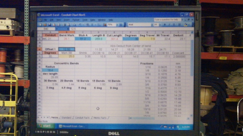
An orange box contains a list. When you click on the orange cell an arrow will appear, when you click on the arrow the list will appear. Select the desired value; the box will close with your chosen value filling the row with the related values visible. In a blue cell, input a measurement for your current task the spreadsheet will calculate the value in a yellow or clear cell. More information about the function of specific cells will be covered in following descriptions.
This sheet uses the standard measuring system. You can input information in decimals or fractions. .
An orange box contains a list. When you click on the orange cell an arrow will appear, when you click on the arrow the list will appear. Select the desired value; the box will close with your chosen value filling the row with the related values visible. In a blue cell, input a measurement for your current task the spreadsheet will calculate the value in a yellow or clear cell. More information about the function of specific cells will be covered in following descriptions.
Each bender has a personality. This sheet contains the Standard information that you input when you make your initial 90 degree bend on the current bender you are using.
Each bender has a personality. This sheet contains the Metric information that you input when you make your initial 90 degree bend on the current bender you are using.
Bending conduit by travel method
There are two pictures on these Facts pages. The first is a measured length of conduit “L” with a deduct mark “A” and a travel mark “B”.
Figure 1
The second is a 90 degree bend on a bending table with a bottom mark “F” and a side mark “E” with marks “Z” added before the conduit is bent and “T” that is added after bend is made, but before pressure is released to include spring back.
Figure 2
We are looking for 5 measurements and ‘Zero”:
Deduct: Deduct is the measurement “AF” in figure 2.
Deduct is a measurement that allows a conduit stub to rise to a desired length.
Place conduit in bender with the “A” mark at the front of the shoe.
“Zero” is when the bender pressure applied has not yet started to bend the conduit, but requires force to rotate the conduit.
Finding “Zero” is very important when using the travel method for bending conduit. When you consistently find the same zero mark for every bend you make, you will be able to repeat bends every time.
Travel: Travel is determined by T=BZ-BT on figure 2
Travel is the distance a conduit is pulled thru the bender to make a 90 degree bend.
With the conduit in the bender at the “Zero” position make mark “Z” at a stationary point at the back of the bender. Document the measurement “BZ”.
Bend a True 90 degree bend. Mark “T” before you release pressure from the bender. Document the measurement “BT”. Subtract BT from BZ. (T=BZ-BT)
Input this value “T” in the Travel column of the Conduit and or Metric Facts sheet for the appropriate size and type of conduit.
Verify on the bending table that you have created a true 90 degree bend.
While the conduit is on the bending table, measure the Deduct length “AF”
Input this value “AF” in the Deduct column of the Conduit and or Metric Facts sheet for the appropriate size and type of conduit.
This measurement is also the minimum stub length that your bender will bend.
Gain: Gain is an increased length of conduit that is created when bending conduit.
Gain is determined by G = (CF + DE) – L
Input this value in the Gain column of the Conduit and or Metric Facts sheet for the appropriate size and type of conduit.
Back to Back: Back to Back is a measurement that is added to the conduit mark that determines the distance between back to back bends. After the first ninety degree bend is made the conduit is removed from the bender and rotates 180 degrees to make the final stub.
The program calculates this measurement and automatically inputs the value into the B to B column.
Back to Back = Deduct – Gain
Input outside diameter of conduit for future use.
The Orange Cell (1A) contains a list of types and sizes of conduit.
Click on cell (1a) and an arrow appears.
Click on arrow and a list appears.
Select type and size of conduit.
List closes showing the type, size and fills column values of conduit selected.
Bend Mark: Cell (1B) Front of Shoe mark.
The cell below the Bend Mark cell (1b) is the calculated value that determines the front of shoe mark for Stub A based on the value input from the cell below 1(c).
Place calculated mark for stub A on conduit
Stub A – Deduct = Bend Mark (at front of shoe).
Input desired stub length in blue box below cell 1(c).
Click left or right arrow or enter key
Calculates bend mark
Length B: Cell 1(d) is the measurement “DE” from figure 2
Input desired length B (“DE”) of conduit into light blue box.
Click left or right arrow or enter key
Calculates cut length
Cut Length: Stub A + Length B – Gain = Cut length
Place calculated mark on conduit for cut length.
Cut and thread conduit at cut length mark before bending
Bend conduit: (See 90 Travel section)
Place conduit in bender with bend mark at front of shoe.
Find “Zero”.
Place the travel mark “T” on the conduit behind the stationary point of the bender.
Bend conduit to travel mark “T”
Verify true 90 degree bend, stub A, and length B values
SPECIAL NOTE: Freeze Pane and Orange Drop down lists
When you open a drop down list and select the “All, top ten, custom, or etc. list, the length of the drop down list is sometimes longer than the screen.
There is a freeze pane inserted after row (42) and sometimes you cannot scroll through the entire list, because of the freeze pane.
When you can’t scroll to your desired information, select the custom feature from the drop down list and create a >”greater than”, or <”less that list” that will encompass your desired values.
You can then click the drop down arrow again.
Select your value with the needed information and continue.
Segment Travel: Travel / 90 x degrees = Segment Travel
Input desired degrees for bend in cell 42(a).
Place conduit in bender and find “Zero”.
Place Segment Travel mark (cell below 1(f)) on conduit behind stationary point of bender.
Bend conduit to Segment Travel mark.
Verify desired degree of bend is attained.
90 Travel: Cell below 1(g). Radius x π/2 = Developed Length = Travel
The distance the conduit is pulled into the bender to attain a 90 degree bend.
Value is copied from the Conduit Facts chart
Place 90 degree travel mark on conduit behind the stationary point at back of bender.
Bend conduit to travel mark.
Verify desired degree of bend is attained.
Bending back to back conduit bends:
Enter desired stub height in blue cell below 1(c) Stub A
Click left or right or enter key
Mark conduit for “A” Bend Mark
Enter distance between Back to Back bend in blue cell below (1d) Length B
Click left or right or enter key
Enter stub length for back to back bend in blue cell below 1(h) BB Stub
Click left or right or enter key
Calculates Back to Back Mark and Back to Back Cut length
Mark conduit for BB mark and BB cut.
All marks are made from Start mark (end of conduit)
Cut and Thread conduit at the BB cut mark
Place conduit in Bender with “A” mark at front of shoe
Find Zero
Mark travel mark “T” on conduit behind stationary point of bender
Attach Cliffhanger Conduit Level on conduit at front of conduit and level
Bend conduit to travel mark “T”
Remove conduit from bender and verify bend and stub length
Place conduit in bender with BB Mark at front of shoe
Find Zero
Level Cliffhanger conduit level so both stub 90’s will be in same plane
Mark travel mark “T” on conduit behind stationary point of bender
Bend conduit to travel mark “T”
Remove conduit from bender and verify bend, stub length and back to back measurements
Reference value is copied from the Conduit Facts chart
Gain
Reference value is copied from the Conduit Facts chart
Back to Back
Reference value is copied from the Conduit Facts chart
Outside Diameter
Reference value is copied from the Conduit Facts chart
Rows 2 thru 37
These Rows contain the values for conduit types and sizes
The values are copied from Facts sheet or calculated with formulas and input values from other cells
Input the desired offset or kick height into the blue cell at Row 40b
Click right or left arrow or enter key
Calculates the value, Mark between bends, in yellow cell in B column
Offset height x cosecant = Mark between bends
Bending Shoe Radius: Columns D thru H
These columns contain the value for the radius of a 90 degree bend for the appropriate size of conduit.
Developed length / π/2 = radius
Degrees: For offsets, kicks, and segment bends
Input desired number of degrees to bend conduit in blue cell 42(a)
Click left or right arrow or enter key
Calculates values for Segment Travel, Mark BB (distance between bends), Shrink and DCOB
Mark BB (yellow cell below 41b)
This is the calculated value for distance between bends for an offset or kick
The overall length of conduit will shrink when you bend an offset or a kick.
The value in cell 42(c) is the measurement you add to the overall cut length of conduit when making an offset or a kick.
DCOB (Kick Deduct from Center of bend)
When you want to kick a conduit with a 90 degree bend on it, the center of the kick bend becomes the adjacent angle of a right triangle. We have created a Deduct from Center of Bend value that allows the hypotenuse of the triangle to meet the adjacent side of the triangle so the desired kick height, or opposite side, will rise to the correct height.
The cells 42(d) thru 42(h) contain the value you deduct from the center of a bend mark to find the front of shoe mark when the bend is less than 90 degrees.
The height of an offset or kick multiplied by the cosecant of the selected angle creates Mark BB (distance between bends).
Determine height of offset and place value in blue cell 40(b)
Click right arrow or enter key
Determine desired degrees to bend conduit to achieve height
Enter value in blue cell 42(a)
Click left, right or enter key
Calculates Mark BB (distance between bends) yellow cell 42(b) and Segment Travel
Mark BB is a center to center measurement.
To create bends in the appropriate place on your conduit you deduct from the center of the “Start” bend mark the value in the DCOB column for the conduit type and size you are bending to find the front of shoe mark. Mark BB is then measured from the Start DCOB mark to place the second bend mark of the offset in the appropriate place.
Place start mark and Mark BB on conduit.
Place conduit in bender with the start DCOB mark at front of shoe.
Find Zero.
Mark conduit for segment travel behind stationary mark at back of bender.
Attach Cliffhanger Conduit Level at back of conduit and level
Bend conduit to segment travel mark and release
Move conduit to second DCOB mark to front of shoe
Find Zero
Rotate conduit 180 degrees and level Cliffhanger Conduit Level at back of conduit.
Mark conduit for segment travel behind stationary mark at back of bender
Bend conduit to segment travel mark and release
Verify height of offset
Bend 90 degree bend with kick:
Enter desired stub A length in blue box below cell (1c)
Place bend mark on conduit
Place conduit into bender
Find zero
Mark conduit for 90 travel behind stationary mark at back of bender
Attach Cliffhanger Conduit Level at back of conduit and level
Bend conduit to 90 travel mark
Verify bend and stub length
Determine height of kick and place value in cell 40(b)
Determine desired degrees to bend conduit to achieve height
Enter value in cell 42(a)
Distance between bends (Mark BB 42(b)) is marked on conduit from back of 90 to center of kick bend
Deduct DCOB and mark conduit
Place conduit in bender with DCOB mark at front of shoe
Find Zero
Determine correct position for 90 degree bend
Level Cliffhanger Conduit Level at back of conduit and level
Mark conduit for segment travel behind stationary mark at back of bender
Bend conduit to segment travel mark and release
Verify height of kick
This chart incorporates the Pythagorean theory a²+b²=c². When you know two sides and an angle you can solve for the other unknowns.
Enter values for sides a, b, and c in known blue cells
Click left or right or enter key
Calculates the unknown side and the degrees for the adjacent and opposite angles
Oblique Triangle Tool (3 Sides)
When you know all three sides the angles can be calculated.
Enter values for sides a, b, and c
Click left or right or arrow key
Calculates the degrees for the unknown angles of the triangle
Sum: Enter a positive number to add or a negative number to subtract into the blue cells of the sum column. Click up or down or enter key. The total will calculate in the yellow cell 61(f).
Multiply: Enter values into blue cells. Click left or right or enter key. The product will be shown in the yellow cell 56(g).
Divide: Enter values into the blue cells. Click left or right or enter key. The product will be shown in the yellow cell 61(g).
A simple table to convert common measurements.
Enter radius of bend in blue cell 65(a)
Click left or right or enter key
Calculates the developed length of bend, and the distance between segment bends for desired degrees of bends
Bending Concentric bends:
Divide developed length into the desired number of bends with the distance between bends marked on conduit
Place conduit in bender with first mark at front of shoe
Find Zero
Attach Cliffhanger Conduit Level at back of conduit
Determine segment travel and mark conduit behind stationary point on bender
Bend conduit to segment travel mark and release
Move to next bend mark
Repeat process until desired radius bend is achieved
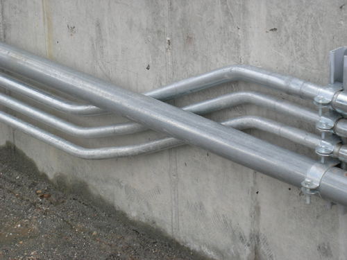
The Cliffhanger Offset is a bend that moves a conduit from one position in a rack to a different position in the rack of conduit. It is a combination of 4 bends that are rotated 90 degrees after each bend. The four bends rotate in a clockwise direction, or the four bends rotate in a counter clockwise direction. The conduit rolls out of the rack offsets up or down and then rolls back into the rack in a different position. Offset “A” (depth) is created with the first and the third bends. Offset “B” (height) is created with the second and the fourth bends.
Step one:
Determine the depth of offset needed to roll the conduit out of the rack. The thickness of the conduit plus a small space is typical, but if an obstruction is in the pathway any depth may be applied.
Enter the value into the blue cell right of the offset one cell in the Cliffhanger offset chart. Determine the degrees to be used for the depth offset and enter the value in the cell below the Degrees cell in the chart. Bends one and three create this offset.
Step two:
Determine the height of the offset required to shift the conduit to its new position. Enter this value into the cell next to offset 2 cell in the chart. Determine the degrees to be used for the height offset and enter the value into the blue cell below the degrees cell in the chart. Bends two and four create this offset.
Step three:
Pick a start mark to begin. All other marks are measured from the start mark. Mark conduit with all four bend marks and place conduit into bender with the start mark at the front of the shoe. Find zero. Attach the Cliffhanger Conduit Level in the end of the conduit away from the bender. Level the conduit.
Step four:
Enter the degrees value for “Offset A” in cell 42(a) (Offset chart) and document the segment travel for offset A. Place the segment travel Mark A1 on the conduit behind stationary point on bender and bend to the mark.
Step five:
Enter the degrees value for “Offset B” in cell 42(a) (Offset chart) and document the segment travel for offset B. Shift conduit to Mark B2 at the front of the shoe. Find zero. Rotate the conduit 90 degrees clockwise and level the attached Cliffhanger Conduit Level. Place the segment travel mark for Offset B on the conduit behind stationary point on bender and bend to the mark.
Step Six:
Shift conduit to Mark A3 at the front of the shoe. Find zero. Rotate the conduit 90 degrees clockwise and level the attached Cliffhanger Conduit Level. Place the segment travel mark for Offset A on the conduit behind stationary point on bender and bend to the mark.
Step Seven:
Shift conduit to Mark B4 at the front of the shoe. Find zero. Rotate the conduit 90 degrees clockwise and level the attached Cliffhanger Conduit Level. Place the segment travel mark for Offset B on the conduit behind stationary point on bender and bend to the mark.
Verify height and width of the Cliffhanger offset.
The information for this set of bends comes out of Richard A Cox’s “Electricians guide to conduit bending”
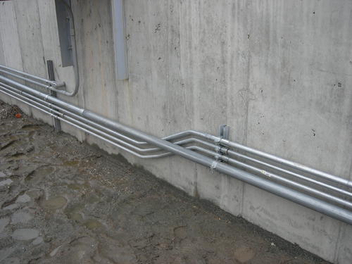
An adjustment must be made to the layout of the second and each subsequent pipe in the group to prevent the ends from being staggered. The adjustment to the start mark is: Adjustment = Center to Center spacing X tangent of ½ the offset angle. All bends should use the same radius for maximum satisfaction.
Step one:
Enter the outside diameter of the conduits used in the parallel offset chart. Enter the desired spacing in the blue cell at 87(b). Enter a start mark measurement or zero if you are starting at the end of the conduit.
Step 2:
Determine the number of degrees desired to create the offsets. Enter value in the offset chart cell 42(b). Click right, left of enter key. This calculates the distance between bends and the segment travel needed for your chosen degree. It also calculates the bend marks for each conduit with the adjustment to each subsequent conduit included in the next conduits marks.
Step 3:
Bend offsets. (Refer to offset section)
These rows and columns contain the values for degrees from 1 to 89, the mark between bends and the cosecant for the all angles.
The values are copied from Facts sheet or calculated with formulas and input values from other cells
The cosecant is the value from a Trigonometric Table based on a selected angle used to find the distance between bends to create offsets and kicks when multiplied by the height of the offset or kick.
Height of offset or kick x cosecant of angle = distance between bends.
Find the angles of Right Triangle by entering values of know sides of triangle into blue cells to determine Sine, Cosine, and Tangent values.
Find value in the Trigonometric Table below to determine angle.
http://www.cliffhangertools.com
801-810-5421